


Best Viewed In
IE,1024x768 Scr. Reso. All rights reserved © Cor-Resist (Nasik) Pvt.Ltd.
2007-08, Powered by Pamtsoft Systems Software,Nashik.
:: Product
::
HCL
GAS ABSORBER..
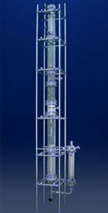
O ne of the
standard operations is the evaporation of liquid wastes. and aggressive flue
gases washing water.Graphite heat exchangers represent the latest in art in the
recovery of acids from industrial wastes. Impregnated graphite material meet the
stringent demands for corrosion resistance imposed on the equipment for
environmental protection measures. They also ensure longer lives and short
downtimes. Owing to aggressiveness of the substances involved,corrosion problems
occur in almost any process aimed at preventing pollutant emmision and
recovering harmful substances from waste gases .
By combining
our expertise in the field of waste gas cleaning with our range of corrosion
resistance materials,we can offer tailor made plant design for your own
particular process: Equipment and complete systems for cleaning hydrogen halide
-containing waste gases and recovery of hydrogen halides. Absorbers for cooling
and subsequent absorbtion of flue and waste gases. We also provide venturi type
or packed collumn scrubbing systems for scrubbing uncondensible waste
gases.
Working
of HCL absorption system in batccessh pro.
For 100kg of total
HCL gas in batch total water requirement to make 30% HCL is 2.33kg for starting
of batch operation initially take 150kg of water in tank below graphite HCL
column (30% HCL tank) with recirculation pump.
Total flow requirement of falling film column given to you to wet properly is 500 Lit/HR this will come from (requirement from 30% HCL tank + fresh water addition from water feeding P/P FRP adiabatic packed absorption column)
Gas get absorbed in wetted wall column till in reaches 20 to 22% concentration so no fresh water addition is required after HCL concentration reaches 20 to 22% fresh water should be added from inlet nozzle regulated proportionally to HCL gas flow from measured 88 kg water kept in vessal above adiabatic column or through pump from vessel at lower level till batch is complete.
Adiabatic column absorbed can absorb fresh water to 20% HCL if proper material balance is regulated and proper wetting of packing takes place
If this balance is not controlled properly unabsorbed gas will get scrubbed in ventury scrubber
Gasses going to adiabatic column for absorption by fresh water when this happens adiabatic column get heated up to 70cel
Liquid from adiabatic column to wetted wall column should go through U seal so that HCL gas does not by pass wetted wall column of go directly to adiabatic column.
Gas flows from HCL inlet nozzle because of suction of ventury. This suction of ventury should be controlled 50MM water column suction at gas inlet and required 150mm water column at suction of ventury
If we have excess suction it has to be controlled by air admit at suction of ventury by pass valve to required suction.
Pressure
+- drop across the system is 100 to 120 mm water column
| · | Regulated water inlet line at top of adiabatic column through Rota meter to regulate flow of water Flow requirement. |
| · | Recirculation flow 500 kg/hr through Rota meters. |
| · | HCL gas inlet through Rota meters (Range – 0-50 kg/hr). |
| · | Note – all 3 Rota meters are required to get more than 20 to 22% concentration at bottom of absorber. |
| · | Liquid outlet line to be dipped more than 0.5 meter in liquid in 30% hcl column tank. |
| · | Outlet Nozzle N-6 should be 2000 mm above liquid level so that liquid drain properly in tank will clear 50 mm Id line. |
| · | 50 mm ID unabsorbed gas line. |
| · | 500 mm H+U seal with 1500 mm heat bellow liquid out line from adiabatic column size U seal 25 NB + Line. |
| · | Gas outlet line 50 NB going to ventury scrubber with part to measure suction of ventury in mm of water column (3/8” BSP). |
| · | By pass line with full part 1 “(+) ball valve to control suction of ventury. |
Commissioning of HCL absorbs system
| · | Start recirculation pump. |
| · | Check flow in flow meter check liquid level in view glass near (N12) with light. |
| · | Check flow of liquid physically at N-6 fer flow of 500 lit/Hr. |
| · | Check size of drain line for absorption line welding gaskets of remove abstpuction. |
| · | Note if still water rises then bigger size to be recommended. |
| · | Check flow 500Lit/Hr.
through N-8 U seal N-6 separately without circulating
pump. |
| · | Again check flow through N – 630 % HCL out let level in 30% view glass. |
| · | Stop circulating pump and check flow through ‘U’ seal with vac of 150 mm water column at venture suction after bypass, 50mm water column at gas inlet. |
| · | No water should come in view glass and water should flow through U seal properly with veutury bypass adjusted. |
| · | Start feeding HCL gas because of load of HCL gas inlet ventury bypass valve to be readjusted to get 150mm of water column. |
| · | After HCL concerted (in 30% HCL tank) reaches 20% start feeing regulated required fresh water from water inlet. |
After
checking above nine points
Cor-resist
provides engineered solutions to meet the needs of virtually any vapor scrubbing
problem, whether its acid gases, NOx, odor control or a myriad of other similar
applications. Our engineers, scientists and designers are capable of tackling
the most complex and difficult problems. Scrubbers are custom designed to meet
your specific performance requirements.
Venturi
scrubbers
.jpg)
The Jet
Venturi Scrubber utilizes a liquid motivated ejector design to entrain
contaminated gases, generally without the need for a blower. The relatively high
liquid-to-gas ratio, liquid atomization, and open internal design provide
effective scrubbing of heavily contaminated gases with minimal maintenance and
virtually unlimited turndown capabilities. It can handle wide ranging conditions
while removing both toxic gases and particulate matter. It is often used as a
first stage in a multi-stage pollution control system. Motivating fluid exits
the nozzle in a hollow cone spray pattern, creating a draft. Contact between the
scrubbing liquid and the gas results in high gas mass transfer and/or
particulate capture. This mixture discharges into a separator.
Material of
Construction : MS,SS304,SS316,POLYPROPYLENE,PVDF,FRB,GRAPHITE
Motive fluid : Caustic Soda/Potash,Water,Lime
Applications : scrubbing Chlorine,Nox,SO2 and other gases
Capacity : We make scrubbers upto 3000 Kg/Hr scrubbing gas
Scrubbing system : An example of out scrubbing system supplied to our clients/P & I Diagram
Motive fluid : Caustic Soda/Potash,Water,Lime
Applications : scrubbing Chlorine,Nox,SO2 and other gases
Capacity : We make scrubbers upto 3000 Kg/Hr scrubbing gas
Scrubbing system : An example of out scrubbing system supplied to our clients/P & I Diagram
| 1. | Start ventury. |
| 2. | Check pressure on top of ventury it should be 2 kg/cm2g. |
| 3. | Check vacuum in mm of water column. |
| 4. | Adjust by pass valve to get 150mm of water column pressure. |